________________________________________________________________________________________________
PARTS CARS USED IN MODEL CONSTRUCTION : Note: No stock height topped 34 Ford has been made in 1:18th scale.
Purchased from Ebay, two 1:18th scale ERTL 34 Ford chopped top hot rod bodies with complete interiors. Cost approximately $20 US and one built ERTL 34 three window coupe model with blown big block and dropped front axle for the use of fenders, hood and grille. This model cost about $30 US and was complete in the box. Also, purchased one Sollido 34 Ford Roadster for front and rear bumpers; cost approximately $25 dollars US. Other detail parts in 1:18th scale needed to complete the model such as a battery, master cylinder, jack , etc., purchased from various suppliers found on Ebay. Purchased one complete Chevrolet V-8 engine in 1/18th scale from Arizona Die Cast, with resin cast dual quad four barrel carburetors and two chrome air cleaners; cost about $10 dollars US. Purchased one ERTL 1940 Ford coupe model on Ebay for $30 dollars US for tires and wheels. Purchased one 1937 Ford Cabriolet by Road Signatures for windshield wipers and side mirrors. That model will be used to build a 1937 Ford Slant Back Sedan, which is Jerry's present street rod.
_________________________________________________________________________________This is a photograph from the Henry Ford Museum archives of a stock 34 Ford three window coupe that was scaled to obtain the proper top height and top profile.

In this photo, the chopped top ERTL model sitting on 34 Ford fenders and the mag wheels that came from the blown ERTL hot rod model. Note, the blown model's frame was used and it had a dropped front. Since Roy's car was stock height, ride height had to be modified on the axle with a spacer to stock height. Also, the blown model had a plastic hood with blower protruding out the top of it and headers coming out the sides of the hood. The hood was modified and used for this build (see later photo).

These are the two donor model bodies. One has already been stripped of its light blue paint, using chemical stripper.

Both bodies have had their paint removed and have started to be marked with felt pen as to where cuts would have to be made to obtain a stock top height. Note the bodies are marked "Host" and "Donor" to avoid confusion as to where the different roof parts need to go.

The bodies were clamped to a work table and the appropriate cuts made with a hand saw and powered Dremel Tool.

Sixth Picture : This picture shows felt pen markings on both bodies of cuts needed to obtain enough material out of one, the one on the Donor roof on the left to be added to the Host body on the right hand side of this photo.

With one top removed, pie shaped cuts were made to begin to obtain the proper top profile. These are the same techniques that would be used on a real car to unchop a top. This is the most difficult part of the unchopping process. An error here would ruin the body being used or would require much more body filler to correct. The corner of the top was bent backward to the right profile.
Note how the thickness of the die cast body varies, depending on location. This makes the cutting effort more difficult.
One of the pictures shows the slit cut in the top necessary to obtain the correct profile.
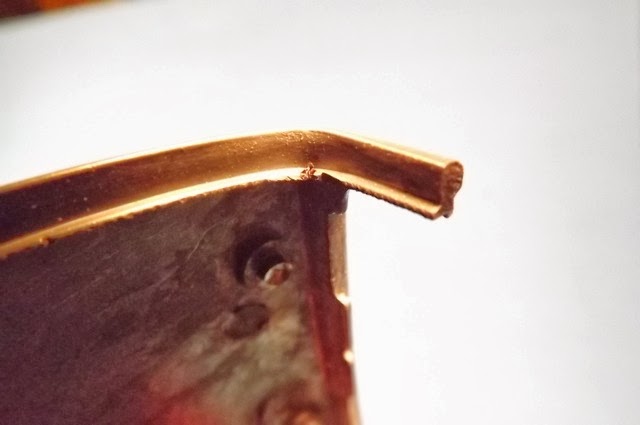
A partial horizontal cut was made, after the vertical slit cut and the die cast metal very carefully bent backward to the desired profile of the back of the roof. A pin has been drilled and installed in the rear roof portion.
In the corner of the front windshield pillar, a partial, very shallow cut was made and the pillar heated with a hair dryer to carefully bend the pillar backward. The pillar will then be drilled and a brass pin epoxied into it for the top to be pinned to the cowl at final assembly.
The front windshield pillar has been drilled and a brass pin epoxied in place for structural rigidity and to make a good bond to the top.
Fortunately, the rear portion of the body metal was thick enough to drill and install a pin. This was done on both sides of the top.
Carefully placing the Donor roof onto the cuts in the Host body, you can see the puzzle of cuts necessary to obtain the correct top profile and height. The Donor roof is pinned and epoxied in place in this picture. The next step in the process is to mix JB Weld and fill in the cuts to eventually obtain a smooth body. Any voids or holes will require another application of JB Weld epoxy. It can be filed and sanded and accepts automotive type lacquer primer surfacer.
A rear roof photo shows the filling and filing that will be necessary to obtain the required rear window opening.
One picture shows the application of JB Weld and the cuts made in the door frame to obtain the proper height to match the now unchopped top. Looking closely, you can see that the door has been drilled and pinned for structural rigidity, since the hinged opening door will be the most delicate part of the model. Additional photos will show door reinforcing details.


Nessun commento:
Posta un commento